

 English
 русский
How to Calculate Stainless Steel Weight: Formulas and Reference Data
The weight of any stainless steel component equals its volume multiplied by its density. Stainless steel density varies slightly by grade, but the standard working figure used across engineering and procurement is 7.93 g/cm³ (7,930 kg/m³) for the most common austenitic grades (304, 316, 316L). Ferritic and martensitic grades run marginally lower at 7.70–7.80 g/cm³.
The basic formula is:
Weight (kg) = Volume (m³) × Density (kg/m³)
For the most common product forms, the volume formula simplifies as follows:
Round Bar / Solid Shaft
Weight (kg) = (D² × 0.00617) × L
Where D = diameter in mm, L = length in meters. The constant 0.00617 incorporates π/4 and the density of 7,930 kg/m³, pre-scaled to accept mm diameter and meter length directly. Example: a 60 mm diameter × 2 m 304 stainless bar weighs 60² × 0.00617 × 2 = 44.4 kg.
Flat Bar / Plate
Weight (kg) = W × T × L × 0.00793
Where W = width in mm, T = thickness in mm, L = length in meters. Example: a 150 mm × 10 mm plate, 3 m long weighs 150 × 10 × 3 × 0.00793 = 35.7 kg.
Hollow Pipe / Tube
Weight (kg) = (OD − WT) × WT × 0.02466 × L
Where OD = outer diameter in mm, WT = wall thickness in mm, L = length in meters. This is the standard formula used for schedule-specified stainless pipe procurement.
Stainless Steel Weight by Grade and Product Form: Reference Table
A reliable stainless steel weight calculator must account for density differences between grades. The table below provides density values and typical weight-per-meter figures for round bar at common diameters, covering the grades most frequently specified in engineering projects.
| Grade | Type | Density (g/cm³) | Ø40 mm bar (kg/m) | Ø80 mm bar (kg/m) | Ø120 mm bar (kg/m) |
|---|---|---|---|---|---|
| 304 / 304L | Austenitic | 7.93 | 9.87 | 39.48 | 88.82 |
| 316 / 316L | Austenitic | 7.98 | 9.93 | 39.74 | 89.41 |
| 321 | Austenitic | 7.90 | 9.83 | 39.32 | 88.47 |
| 410 / 420 | Martensitic | 7.75 | 9.64 | 38.56 | 86.76 |
| 430 | Ferritic | 7.70 | 9.58 | 38.32 | 86.21 |
| 17-4 PH (630) | Precipitation-hardening | 7.78 | 9.68 | 38.72 | 87.12 |
For procurement and shipping purposes, always add a 3–5% over-tolerance allowance to calculated weights to account for mill tolerance on diameter and length (per ASTM A484 and EN 10060 standards for round bar). Custom-forged components require weight estimation from engineering drawings rather than standard tables.
What Does "Forged by Steel" Mean and Why It Matters for Engineering Components
Steel that is forged — shaped under compressive force at elevated temperature rather than cast in a mold — develops a fundamentally different internal structure from cast or machined-from-bar alternatives. Forging aligns the grain flow with the shape of the finished part, eliminating the random crystal orientation of cast steel and the abrupt grain boundaries left by machining across bar stock.
The mechanical benefits of forged steel over cast or machined equivalents are well-documented:
- Higher impact toughness — Charpy impact values for forged steel components are typically 20–40% higher than cast equivalents at the same nominal composition, because forging breaks up casting porosity and segregation.
- Better fatigue resistance — Oriented grain flow reduces stress concentration at subsurface defect sites. Forged shafts and flanges show fatigue lives 2–3× longer than castings in cyclic load applications.
- Tighter dimensional consistency — Die forging holds closer tolerances than sand casting, reducing rough machining stock and downstream finishing costs.
- No internal porosity or shrinkage voids — A persistent risk in castings that can cause catastrophic failure under pressure or shock load.
These advantages make forged steel the mandatory specification for high-consequence applications: pressure vessel flanges (ASTM A182), crankshafts, gear blanks, valve bodies, and rotating shafts in turbomachinery.
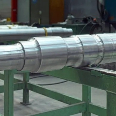
Forged Steel Shafts: Grades, Processes, and Application Requirements
A forged steel shaft is produced by open-die or closed-die forging of a steel billet, followed by controlled cooling or heat treatment to develop the required mechanical properties, and then precision machining to final dimensions. The choice of steel grade and forging process depends on the service environment.
Common Steel Grades for Forged Shafts
- Carbon steel (AISI 1045, 1060) — The standard choice for general industrial shafts. 1045 delivers a good balance of tensile strength (~620 MPa annealed, up to 850 MPa quenched and tempered) and machinability at low cost. Used in pump shafts, conveyor drives, and general machinery.
- Alloy steel (4140, 4340) — Chromium-molybdenum and nickel-chromium-molybdenum grades for high-performance shafts. 4340 reaches tensile strengths of 1,000–1,400 MPa after heat treatment, with excellent toughness. Standard in aerospace landing gear, large press shafts, and marine propulsion.
- Stainless steel (316, 17-4 PH, 410) — Specified when the shaft operates in corrosive media (seawater, chemicals, food processing). 17-4 PH forged shafts achieve tensile strengths of 930–1,310 MPa depending on condition (H900 through H1150), combining corrosion resistance with high strength. 316 forged shafts are preferred for centrifugal pumps handling aggressive liquids.
- Tool steel (H13, D2) — For shafts and spindles subject to extreme wear or operating at elevated temperatures, such as in hot extrusion presses and die casting equipment.
Open-Die vs. Closed-Die Forging for Shafts
Open-die forging (also called free forging or smith forging) uses flat or simple-profile dies that do not fully enclose the billet. The operator repeatedly repositions and rotates the billet under a hydraulic press or hammer to shape it progressively. This process is standard for large shafts — diameters above 150 mm and lengths up to several meters — where die costs for closed-die tooling would be prohibitive. Open-die forged shafts have excellent grain refinement throughout the cross-section but require more machining to reach final dimensions.
Closed-die forging uses matched die sets that define the near-net shape in a single or few strokes. It is economical for medium-sized shafts produced in high volumes — step shafts, flanged shafts, and splined shafts for automotive and agricultural applications. Die tooling costs ($5,000–$50,000 per die set depending on complexity) are amortized over production runs of 500–50,000 parts.
Quality Standards and Inspection for Forged Shafts
Critical forged steel shafts are subject to a combination of the following inspection methods before dispatch:
- Ultrasonic testing (UT) — Detects internal defects (forging laps, residual porosity, segregation bands). Required per ASTM A388 for pressure-containing and rotating components above a defined diameter threshold.
- Magnetic particle inspection (MPI) — Surface and near-surface crack detection for ferromagnetic steels. Standard for gear blanks and shaft fillets.
- Mechanical testing (tensile, hardness, Charpy impact) — Performed on test coupons cut from forging prolongations or separately forged representative pieces per ASTM A370.
- Chemical composition verification — OES spectrometer analysis of heat composition against the specified grade limits. Material test certificates (MTC / Mill Cert) per EN 10204 3.1 or 3.2 are standard deliverables for critical applications.
Weight Estimation for Forged Stainless Steel Shafts: Practical Approach
Estimating the weight of a forged stainless steel shaft before final machining requires accounting for two factors that do not apply to standard bar stock: forging allowance and rough machining stock.
A typical stainless steel weight calculator for a forged shaft works through the following steps:
- Calculate the finished part volume from the engineering drawing, treating the shaft as a series of cylinders (one per diameter step) and summing their volumes.
- Add machining allowance — Typically 5–15 mm per face on open-die forgings, or 2–6 mm per face on closed-die. Add this to every diameter and length dimension before calculating the forging volume.
- Apply a flash and scale loss factor — For closed-die forging, add 10–20% to the net forging weight to estimate the required billet weight (accounts for flash trim loss and scale). For open-die, the factor is 5–12%.
- Multiply by grade density — Use the appropriate density from the table above (e.g., 7.98 g/cm³ for 316 stainless).
As a worked example: a 316 stainless steel forged shaft with a finished volume of 2,800 cm³, machined from a closed-die forging with 8 mm per-face allowance and 15% billet factor, will require a starting billet of approximately 3,700 cm³ × 7.98 g/cm³ = 29.5 kg, versus the finished shaft weight of approximately 22.3 kg. The difference — the buy-to-fly ratio — is a key cost driver in stainless shaft procurement and is why near-net-shape forging is commercially preferred over machining from oversized bar for larger components.


