

 English
 русский
Why Shafts Are Forged: The Metallurgical Case for Forging Over Machining
A forged steel shaft is produced by plastically deforming a heated steel billet under compressive force — through open-die hammering, press forging, or rotary forging — to achieve a finished or near-finished shape. The process is fundamentally different from machining a shaft from bar stock, and the mechanical property differences between the two methods are significant enough to determine material selection in every safety-critical rotating application.
When steel is forged, the plastic deformation refines the grain structure, closes internal porosity and voids present in the original ingot, and aligns the metal's grain flow (fiber flow) along the contours of the part. In a forged shaft, the grain runs continuously along the shaft's length and follows any steps, shoulders, or flanges — creating an uninterrupted fibrous structure that resists crack initiation and propagation. In a machined bar stock shaft, the grain runs uniformly through the bar, meaning any cross-sectional cut (such as a shoulder or keyway) severs grain lines and creates a potential crack initiation site.
The practical results of this difference are measurable: forged steel shafts typically exhibit 20–30% higher fatigue strength, 15–20% higher impact toughness, and superior resistance to stress corrosion cracking compared to machined equivalents in the same alloy. For shafts subjected to torsional fatigue, bending loads, and cyclic stress — which describes virtually every power transmission and propulsion shaft in service — these improvements translate directly into longer service life and reduced catastrophic failure risk.
Forging the Shaft: Process Methods and Their Applications
The method used for forging the shaft depends on the shaft's dimensions, geometry complexity, required tolerances, and production volume. Three primary forging processes are applied to shaft production:
Open-Die Forging
In open-die forging, a heated ingot or billet is worked between flat or simple contoured dies while being incrementally rotated and repositioned by the operator or manipulator. The dies do not fully enclose the workpiece — hence "open die." This method is used for large shafts that exceed the size limits of closed-die equipment: propeller shafts for ships, turbine rotor shafts, large generator shafts, and mill rolls. Open-die forged shafts can reach lengths exceeding 15 meters and weights of 100 metric tons or more. The grain refinement and void closure benefits of forging are fully realized in this process, and the flexibility of open-die tooling makes it cost-effective for low-volume, large-dimension shaft production.
Closed-Die (Impression-Die) Forging
Closed-die forging uses matched die sets that define the final shaft geometry, forcing heated steel to fill the die cavity under high pressure. This method achieves tighter dimensional tolerances and more complex near-net shapes than open-die forging, reducing post-forge machining requirements. It is economically suited for medium-volume production of shafts with consistent dimensions — automotive axle shafts, turbine compressor shafts, and hydraulic pump shafts are common examples. Flash (excess material squeezed from the die parting line) is trimmed after forging.
Rotary (Radial) Forging
Rotary forging uses multiple radially arranged dies that simultaneously strike the workpiece as it is fed axially through the die set, reducing the diameter incrementally along the length. This method produces stepped shafts, tapered shafts, and hollow shafts with exceptional dimensional consistency and surface finish. It is used for precision aerospace shafts, drive shafts, and the production of forged step shafts where multiple diameter changes must be held to close tolerances. Rotary forging applies forging's grain refinement benefits while achieving surface finishes approaching that of a turned bar, significantly reducing finishing costs.
Propeller Shaft Forging: Marine and Aerospace Requirements
Propeller shaft forging is one of the most demanding shaft applications in engineering. A marine propeller shaft must transmit the full torque output of the vessel's main engines to the propeller — potentially thousands of kilowatts in a large commercial vessel — while enduring continuous bending loads from propeller weight and hydrodynamic forces, torsional fatigue from propeller thrust fluctuations, and the corrosive environment of seawater at the stern tube.
For marine propeller shafts, open-die forging from a killed, vacuum-degassed steel ingot is the standard production route. Common alloy selections include carbon steel grades such as AISI 1045 and 1050 for smaller vessels, and alloy steels such as 4140 (Cr-Mo), 4340 (Ni-Cr-Mo), and stainless grades such as 316L or duplex 2205 for corrosive environments or premium applications. Classification societies including Lloyd's Register, DNV GL, and ABS specify material grades, forging procedures, ultrasonic testing standards, and mechanical property requirements that forged propeller shafts must satisfy before installation.
Key dimensional features of a forged propeller shaft include the propeller taper at the outboard end (where the propeller boss seats and is locked by a propeller nut), the intermediate bearing journal (a precision-ground cylindrical section supported by the stern bearing), and the inboard flange or coupling that connects to the gearbox output shaft. All these features are forged integral with the shaft — welded construction is not accepted by classification societies for propeller shaft flanges on commercial vessels.
Aerospace Propeller Shaft Forgings
In aircraft with piston or turboprop engines, the propeller shaft transmits engine power to the propeller hub and must also withstand gyroscopic bending moments as the aircraft maneuvers. Aerospace propeller shaft forgings are produced from high-strength alloy steels (4340, 300M) or titanium alloys (Ti-6Al-4V) for weight-critical applications, with AMS material and process specifications governing forging, heat treatment, non-destructive testing, and dimensional inspection. The fatigue life of an aerospace propeller shaft is typically certified to a defined number of flight cycles, after which mandatory replacement is required regardless of apparent condition.
Forged Rotor Shaft: Power Generation and Industrial Rotating Machinery
A forged rotor shaft is the central structural element of a rotating machine — a turbine, generator, compressor, or electric motor — around which the active components (turbine blades, generator windings, impeller stages) are assembled or directly mounted. The rotor shaft carries the combined dynamic loads of the rotating assembly, transmits torque from the driving prime mover to the load, and maintains dimensional stability across wide temperature and speed ranges over service lives measured in decades.
In steam and gas turbines, forged rotor shafts represent some of the most technically demanding large forgings produced. A large steam turbine rotor shaft may be 10–15 meters in length, weigh 50–150 metric tons, and be required to operate continuously at 3,000 or 3,600 RPM (for 50 Hz and 60 Hz grid synchronization respectively) at elevated temperatures up to 600°C in the high-pressure turbine section. The steel selected — typically a Cr-Mo-V low-alloy grade such as 26NiCrMoV14-5 or 30CrMoV9 — must retain adequate creep resistance, high-temperature tensile strength, and fracture toughness at operating temperature while resisting embrittlement over a 30–40 year design life.
The forging process for large rotor shafts begins with vacuum induction melting (VIM) followed by vacuum arc remelting (VAR) or electroslag remelting (ESR) to achieve the chemical homogeneity and cleanliness required for high-cycle fatigue applications. The refined ingot is then open-die forged with multiple reheating cycles to work the material through to the center of the cross-section — ensuring that the core of a large-diameter shaft receives the same grain refinement as the surface. Ultrasonic testing (UT) to detect internal defects is mandatory at multiple stages of production, with acceptance criteria defined by standards such as EN 10228-3, ASTM A388, and customer-specific specifications.
Electric Motor and Generator Rotor Shafts
For electric motors and generators in the small-to-medium size range, forged rotor shafts are produced from medium-carbon alloy steels (4140, 4340) or micro-alloyed steels by closed-die or rotary forging. The shaft must provide precise bearing journal surfaces, maintain concentricity of the rotor stack mounting diameter to within tight runout tolerances, and resist the torsional shock loads associated with motor starting and load transients. In high-speed applications such as turbo-generators and aerospace motor-generators, titanium alloy rotor shafts are used to minimize rotating mass and reduce bearing loads.
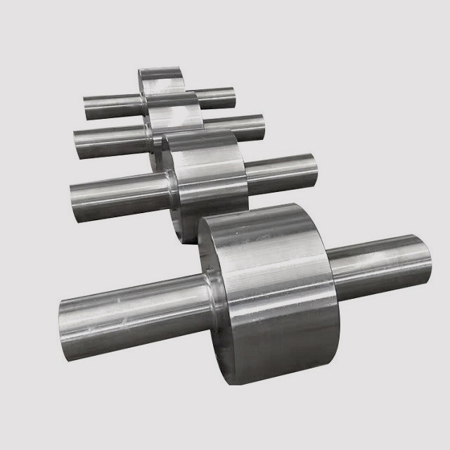
Forged Step Shaft: Multi-Diameter Geometry and Design Considerations
A forged step shaft — also called a stepped shaft or multi-diameter shaft — features two or more distinct cylindrical sections of different diameters along its length, created integral during the forging process rather than produced by machining down a uniform bar. Each diameter change creates a shoulder or step, which serves functional purposes: locating a bearing inner race, providing a face for a gear or pulley hub to seat against, transitioning from a larger torque-transmitting section to a smaller journal, or accommodating a sealing surface.
From a structural standpoint, the shoulder of a step shaft is a stress concentration point. The stress concentration factor (Kt) at a shaft shoulder depends on three geometric parameters: the ratio of the large diameter to the small diameter (D/d), the fillet radius at the shoulder (r), and the applied load type (bending, torsion, or axial). A sharp-cornered shoulder (r/d → 0) can produce Kt values of 2.5–3.5 in bending — effectively reducing the local fatigue strength to one-third of the nominal material value. Properly proportioned fillet radii (typically r/d ≥ 0.1 is recommended for rotating shafts) reduce Kt to 1.3–1.7, recovering the majority of the base material fatigue performance.
Forging a step shaft rather than machining it from oversized bar stock provides two compounding benefits at the shoulder region: the grain flow follows the contour of the step (rather than being cut transversely by machining), and the forging process introduces beneficial compressive residual stresses at the surface that oppose the tensile fatigue stresses generated in service. These effects combine to make forged step shafts substantially more fatigue-resistant than machined equivalents at stress concentration features — which is precisely where fatigue failures initiate in service.
Common Applications and Alloy Selection
- Gearbox input and output shafts: Forged from 4140 or 4340 alloy steel, heat-treated to 28–34 HRC, with multiple diameter steps for bearing journals, gear mounting bores, and coupling flanges. Case hardening (carburizing or nitriding) of gear tooth zones is applied after rough machining.
- Automotive axle shafts: Forged stepped shafts in 1541 or 4140 with a large flange at the outboard end for the wheel hub, a reduced journal section through the differential carrier bearing, and a splined inner end engaging the differential side gear.
- Pump and compressor shafts: Forged 316 stainless or duplex stainless step shafts for corrosive service, with precision-ground bearing journals and impeller mounting steps held to h6 or js6 tolerance for interference fit assembly.
- Wind turbine main shafts: Large-scale open-die forged step shafts in 42CrMo4 or S34MnV, connecting the rotor hub to the gearbox input. These can be 2–4 meters in length and weigh 10–25 metric tons, with bearing journal diameters exceeding 500 mm.
Forged Step Shaft vs. Machined Step Shaft: Key Differences
| Property | Forged Step Shaft | Machined from Bar Stock |
|---|---|---|
| Grain flow at shoulders | Continuous, follows contour | Severed transversely at each step |
| Fatigue strength | 20–30% higher | Baseline |
| Surface residual stress | Compressive (beneficial) | Tensile or neutral |
| Material waste | Low (near-net shape) | High (large diameter bar required) |
| Lead time for large sizes | Longer (forging + heat treat) | Shorter (bar stock availability) |
| Preferred for | High-cycle fatigue, safety-critical | Prototypes, low-load, short-run |


