

 English
 русский
What Is a Forged Rolling Shaft?
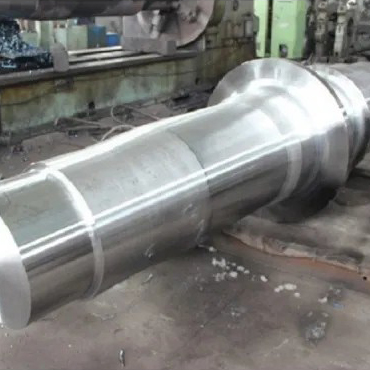
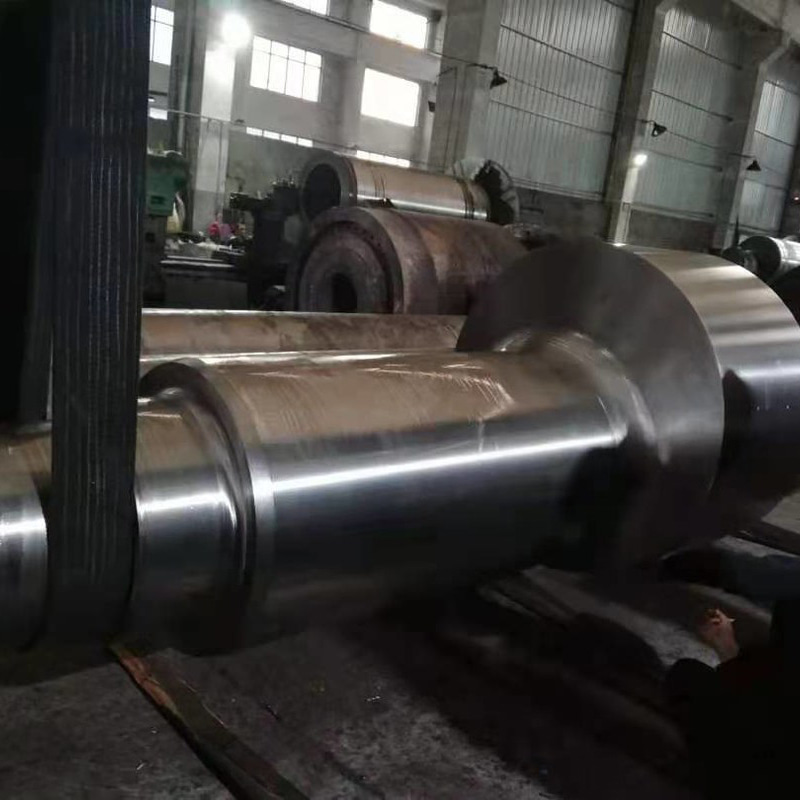
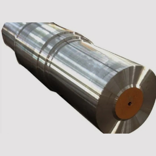
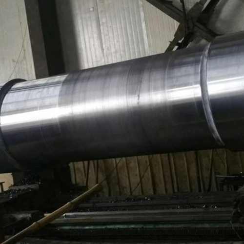
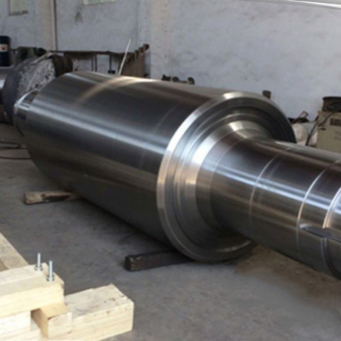
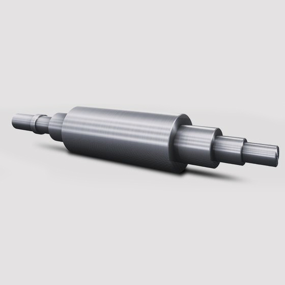
A forged rolling shaft is a rotating or load-transmitting cylindrical component produced through a forging process — in which a heated steel billet is shaped under high compressive force — rather than by casting or machining from bar stock alone. The combination of the forging method with the subsequent precision machining and heat treatment steps produces a shaft with superior mechanical integrity compared to cast or simply turned alternatives, making forged shafts the standard specification in high-load, high-cycle rolling applications such as rolling mill equipment, conveyor drive systems, heavy press machinery, and power transmission drivetrains.
The defining characteristic of a forged shaft is its refined grain structure. During forging, the compressive working of the hot steel breaks down the coarse dendritic grain structure inherent in cast billets and re-orients the grain flow lines along the contour of the part. This results in a homogeneous, fine-grained microstructure with consistent mechanical properties throughout the cross-section — a critical advantage for shafts that must sustain millions of load cycles in rolling contact or torsional fatigue environments without crack initiation or propagation.
In rolling mill and heavy industrial contexts, the term "rolling shaft" encompasses several related components — work roll shafts, backup roll shafts, pinion shafts, and conveyor drive shafts — all of which share the requirement for high fatigue resistance, dimensional precision at bearing journals and coupling interfaces, and reliable performance under combined bending, torsion, and radial loading.
Forging Methods Used in Rolling Shaft Production
Several forging processes are used to produce rolling shafts, each suited to different size ranges, production volumes, and mechanical property requirements. The selection of forging method directly affects grain flow quality, dimensional accuracy of the forged blank, and the extent of subsequent machining required.
Open-Die Forging (Free Forging)
Open-die forging is the dominant process for large rolling shafts — particularly those exceeding 500 mm in diameter or several meters in length — where closed-die tooling would be impractical due to the scale and weight involved. A heated ingot or billet is progressively worked between flat or simple-profile dies on a hydraulic press or forging hammer, with the operator rotating and repositioning the workpiece between each press stroke to achieve the target shape and cross-section.
The key process parameter in open-die shaft forging is the forging ratio — the ratio of the original cross-sectional area of the ingot to the final cross-sectional area of the forged shaft. A minimum forging ratio of 3:1 to 4:1 is generally required to fully break down the cast ingot structure, close internal porosity, and develop the refined grain structure that gives forged shafts their mechanical advantage over castings. For critical applications such as large rolling mill backup roll shafts, forging ratios of 5:1 or higher are specified to ensure the deepest possible grain refinement through the full cross-section.
Open-die forging produces shafts with generous machining allowances — typically 20–50 mm per surface on large parts — which are then removed by rough and finish turning, grinding, and precision machining of bearing seats, keyways, and coupling splines to final dimensional tolerances.
Closed-Die Forging (Impression Die Forging)
For smaller rolling shafts produced in higher volumes — such as transmission input shafts, pinion shafts in gearboxes, and drive shafts in automated conveyor systems — closed-die forging offers superior dimensional consistency and near-net-shape output. The billet is compressed within matched die halves that contain the full negative profile of the shaft, including stepped diameters, flanges, and integral features. The process requires significant upfront tooling investment but drastically reduces per-piece machining time and material waste compared to open-die forging.
Modern closed-die forging of shafts is often performed in multiple progressive stages — pre-form, blocker, and finisher — to distribute metal flow gradually and avoid defects such as laps, cold shuts, or incomplete fill in thin sections.
Rotary Forging and Radial Forging
Radial forging — in which multiple dies arranged radially around the workpiece strike simultaneously as the billet rotates and advances axially — is particularly well suited to long shaft production. The process delivers uniform deformation around the full circumference at each axial position, producing exceptionally consistent grain structure and dimensional accuracy along the entire shaft length. Radial forging is increasingly specified for high-precision rolling mill work roll shafts and for large power generation rotor shafts where symmetrical mechanical properties in all radial directions are critical.
Material Selection for Forged Rolling Shafts
The steel grade selected for a forged rolling shaft must satisfy the combined demands of the application: sufficient core strength and toughness to resist bending and torsional fatigue, adequate surface hardness after heat treatment to resist wear at bearing journals and contact zones, and good forgeability to allow complete grain refinement during the forging operation. The following grades represent the most widely specified materials across the industry.
| Steel Grade | Standard | Tensile Strength (QT) | Key Properties | Typical Application |
|---|---|---|---|---|
| 42CrMo4 (4140) | EN 10083 / AISI | 900–1,100 MPa | High fatigue strength, good hardenability, excellent toughness | General rolling shafts, pinion shafts, drive shafts |
| 34CrNiMo6 (4340) | EN 10083 / AISI | 1,000–1,200 MPa | Superior deep hardenability for large cross-sections, high impact toughness | Large rolling mill shafts, heavy press drive shafts |
| 18CrNiMo7-6 | EN 10084 | 1,100–1,300 MPa (case) | Case-carburizing grade; hard surface with tough core after carburizing + quench | Gear shafts, pinion shafts requiring high surface hardness |
| 50CrMo4 | EN 10083 | 1,000–1,200 MPa | High wear resistance at journals, good fatigue limit | Work roll shafts, conveyor drive shafts |
| S34MnV (Microalloyed) | Various | 800–1,000 MPa | Controlled-cooling strengthening; eliminates quench-and-temper heat treatment | High-volume automotive and machinery shafts |
Material Cleanliness and Inclusion Control
For large or highly stressed rolling shafts, the steel's cleanliness — specifically the size, distribution, and type of non-metallic inclusions — is as important as the alloy composition. Inclusions act as stress concentration sites that initiate fatigue cracks under cyclic loading. Premium shaft steels are produced via vacuum degassing (VD) or vacuum arc remelting (VAR) processes that dramatically reduce oxygen and sulfur content, minimizing inclusion count. Ultrasonic testing of forged shaft blanks to SEP 1921 Class C/c or better is standard for critical rolling mill and power generation shaft applications, ensuring that no significant inclusions are present in the high-stress bore and journal regions before machining investment is committed.
Heat Treatment of Forged Rolling Shafts
Forging alone does not achieve the final mechanical properties required for service. A carefully controlled heat treatment sequence following forging is essential to develop the target combination of core strength, surface hardness, and residual stress state.
Normalizing or Annealing After Forging
Immediately after forging, large shafts are either normalized (air-cooled from austenitizing temperature) or soft-annealed to relieve forging stresses, homogenize the microstructure, and reduce hardness to a level suitable for rough machining. Controlled slow cooling in furnaces is mandatory for alloy steel shafts above approximately 150 mm diameter to prevent quench cracking from thermal gradients during the forging cooling phase.
Quench and Temper
Quench and temper (Q&T) is the primary strengthening treatment for medium carbon and alloy steel rolling shafts. The shaft is austenitized at 820–900°C (depending on grade), then quenched in oil, water, or polymer quench medium to transform the austenite to martensite throughout the cross-section. The depth of full martensite transformation — determined by the steel's hardenability and the shaft diameter — governs the achievable core hardness and strength. Tempering follows immediately at 550–680°C to convert the brittle as-quenched martensite to tempered martensite, achieving the target tensile strength and impact toughness combination specified for the application.
For large shaft diameters, through-hardening becomes increasingly difficult as diameter increases, because the quench rate at the core inevitably slows. 34CrNiMo6 (4340) and similar high-hardenability nickel-chromium-molybdenum grades are specified precisely because their hardenability allows full martensite transformation in sections up to 200–300 mm diameter, maintaining consistent properties from surface to core.
Surface Hardening at Bearing Journals
Rolling shafts frequently require a harder surface at bearing journal diameters and any rolling contact zones than the quench-and-tempered core alone can provide. Induction hardening is the dominant surface hardening method — a high-frequency induction coil heats only the surface layer of the journal to austenitizing temperature in seconds, which is then immediately quenched to produce a hard martensitic case of 55–62 HRC over a tough, lower-hardness core. Case depths of 3–10 mm are typical for rolling shaft journals, with the depth controlled by induction frequency, power density, and heating duration. The compressive residual stresses introduced by the surface expansion during quenching also contribute beneficially to the journal's rolling contact fatigue life.
Quality Inspection and Testing Standards
A forged rolling shaft destined for a critical application passes through a defined sequence of inspections before dispatch — each targeting a specific failure mode relevant to the shaft's service loading.
Ultrasonic testing (UT) is performed on the rough-machined or finish-machined blank to detect internal inclusions, forging laps, or segregation zones that are invisible on the surface. Large shafts are typically tested to EN 10228-3 or EN 10228-4 (for ferritic and martensitic steel forgings respectively), with acceptance criteria defined by indication class and reflection amplitude relative to a reference reflector. For the most critical applications — such as nuclear plant shafts and large offshore wind turbine main shafts — 100% volumetric UT with automated scanning systems is specified.
Magnetic particle inspection (MPI) is applied to detect surface and near-surface cracks, particularly at stress concentration features such as fillet radii, keyways, and thread runouts. After induction hardening of bearing journals, MPI is repeated at the hardened zones to detect any quench cracks before the shaft proceeds to finish grinding.
Mechanical testing — tensile, impact (Charpy V-notch), and hardness — is performed on test coupons cut from a prolongation integral with the forging or from a separately forged test piece treated identically to the production part. Results are reported in a material test certificate conforming to EN 10204 Type 3.1 or 3.2, depending on whether customer-witnessed inspection is required. Hardness traverses at the journal bore confirm achieved case depth and core hardness after induction hardening.
Dimensional inspection using coordinate measuring machines (CMM) or precision bench measurement confirms journal diameters to specified tolerances (typically h5 or h6 for bearing fits), surface roughness at journals (Ra 0.4–0.8 µm for rolling element bearing seats), runout (TIR typically ≤0.02 mm on precision shaft journals), and straightness along the shaft axis. For shafts subject to dynamic balancing requirements, residual unbalance is verified on a dynamic balancing machine before final inspection sign-off.
Forged vs Cast Rolling Shafts: Why Forging Is the Industry Standard
The superiority of forged rolling shafts over cast alternatives in high-load applications is not a matter of preference — it is supported by consistently documented mechanical property data across multiple decades of industrial testing.
Cast steel shafts contain solidification shrinkage porosity, dendritic segregation of alloying elements, and random grain orientation — all of which reduce fatigue strength and impact toughness relative to the same nominal alloy in forged form. Published comparative data for medium carbon alloy steels consistently shows that forged components achieve 20–35% higher fatigue endurance limits and 40–60% higher Charpy impact values at equivalent hardness compared to castings. In rotating shaft applications where fatigue loading drives the design, this difference directly translates to a longer service life or a reduction in required shaft diameter — and with it, a reduction in bearing load and system inertia.
For rolling mill work roll shafts, backup roll necks, and heavy conveyor drive shafts — components where a single in-service failure can halt an entire production line and cause multi-day unplanned downtime at significant commercial cost — the incremental premium of forging over casting represents a straightforward economic justification. The total cost of ownership calculation, including unplanned downtime risk, consistently favors forged rolling shafts in any application operating above moderate duty cycle or load levels.