

 English
 русский
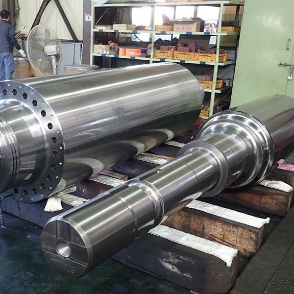
What Is a Steel Eccentric Shaft?
A steel eccentric shaft is a precision-machined rotating component in which one or more journals, lobes, or cylindrical sections are offset from the shaft's central rotational axis by a deliberate, fixed distance known as the eccentricity or throw. When the shaft rotates, the offset section traces a circular path around the true center, converting continuous rotary motion into controlled reciprocating or oscillating motion in the mechanism it drives.
Steel is the dominant material for eccentric shafts because it combines the tensile strength needed to withstand bending loads, the surface hardness required for wear resistance at bearing interfaces, and the machinability that allows tight dimensional tolerances to be achieved and maintained. Depending on the application, grades ranging from medium-carbon steel to case-hardened alloy steel and stainless variants are specified. The geometry may appear simple, but the eccentricity dimension and concentricity tolerance between journals are among the most tightly controlled measurements in precision shaft manufacturing — errors measured in microns directly affect motion accuracy, vibration levels, and component service life.
How an Eccentric Shaft Works: The Motion Conversion Principle
The operating principle is straightforward but powerful. A bearing or follower is mounted on the eccentric section of the shaft. As the shaft rotates about its true axis, the eccentric journal moves in a circle whose radius equals the eccentricity value. Any component connected to that bearing — a connecting rod, a push rod, a pump piston, a press ram — is constrained to follow that circular displacement in one plane, producing a stroke equal to twice the eccentricity.
For example, an eccentric shaft with a 5 mm offset from center produces a 10 mm stroke in the driven mechanism per full revolution. By changing the eccentricity at the design stage, engineers directly control the stroke length without altering the rotational drive system. This makes the eccentric shaft a uniquely compact and adjustable motion generator — in some designs, the eccentricity is intentionally made adjustable via a phase-adjustable collar, allowing stroke length to be tuned during operation.
The motion profile differs from a simple crank. A crank drives a connecting rod through a pin offset at its end; an eccentric shaft drives a surrounding bearing or strap that encircles the eccentric journal entirely. This full encirclement distributes load over a larger contact area, making the eccentric shaft arrangement particularly suited to high-force, low-clearance applications.
Key Applications Across Industries
Steel eccentric shafts appear across a remarkably wide range of machinery. Their ability to convert rotary to reciprocating motion precisely and compactly makes them irreplaceable in the following fields:
- Jaw crushers and cone crushers — In aggregate processing and mining equipment, the eccentric shaft is the core component that drives the crushing jaw or mantle in its oscillating path. The shaft must withstand enormous cyclic bending and torsional loads; heavy-section alloy steel forgings with case-hardened journals are standard. Eccentricity determines the crusher's throw and, consequently, its output gradation and throughput.
- Reciprocating compressors and pumps — Eccentric shafts drive pistons in low-speed reciprocating compressors and diaphragm pumps. The full-encirclement bearing arrangement minimizes side loading on the piston rod, extending seal life compared with crank-pin designs.
- Stamping and punching presses — Mechanical presses use eccentric shafts (or eccentric gears) to drive the ram. The eccentric's geometry defines the press stroke; the shaft must absorb the full punch-through shock load at bottom dead center on every cycle.
- Wankel rotary engines — The output shaft of a Wankel engine is an eccentric shaft. The rotor orbits the eccentric journal, and the shaft's offset geometry defines the engine's swept volume and power stroke geometry.
- Textile machinery — Weaving looms and knitting machines use eccentric shafts to drive heddle frames, needle bars, and take-up mechanisms in precisely timed reciprocating motions coordinated with the main shaft's rotation.
- Medical and laboratory equipment — Orbital shakers, centrifuges with offset rotors, and certain surgical instrument drives rely on small-diameter eccentric shafts machined to sub-micron tolerances from stainless or tool steel.
Steel Grades Used in Eccentric Shaft Manufacturing
Material selection is driven by the load magnitude, surface hardness requirement, operating environment, and whether the shaft is subjected to impact loading. The most commonly specified grades are:
| Steel Grade | Typical Standard | Key Properties | Common Applications |
|---|---|---|---|
| Medium-carbon steel | AISI 1045 / C45 | Good machinability, moderate strength, induction-hardenable | General-purpose compressors, pumps, light presses |
| Chromium-molybdenum alloy steel | AISI 4140 / 42CrMo4 | High tensile strength, excellent fatigue resistance, through-hardenable | Jaw crushers, heavy presses, high-cycle machinery |
| Nickel-chromium-molybdenum steel | AISI 8620 / 20NiCrMo2 | Case-carburizing grade, hard surface over tough core, impact resistant | Rotary engines, gearbox-integrated eccentric shafts |
| Stainless steel | AISI 440C / 316 | Corrosion resistance, cleanroom compatible | Food processing, medical devices, marine equipment |
For crusher shafts and other high-impact applications, the blank is typically produced as a forging rather than turned from bar stock. Forging aligns the grain structure of the steel with the shaft geometry, significantly improving fatigue strength and impact toughness compared with a machined billet. Non-destructive testing — ultrasonic inspection or magnetic particle inspection — is standard practice for safety-critical shafts before finish machining begins.
Manufacturing Process and Critical Tolerances
Producing a steel eccentric shaft to specification requires a sequence of machining, heat treatment, and finishing operations, each contributing to the final dimensional accuracy and surface quality of the bearing journals.
- Turning and rough machining — The shaft blank is center-drilled on both its true axis and its eccentric axis. Rough turning removes the bulk of material with generous stock allowance for subsequent heat treatment distortion.
- Heat treatment — Induction hardening, case carburizing, or through-hardening is applied to achieve the specified surface hardness (typically HRC 55–62 for journal surfaces) while maintaining core toughness. Heat treatment introduces dimensional changes that must be accounted for in pre-treatment stock allowances.
- Grinding — Cylindrical grinding of the eccentric and main journals to final dimensions is the most critical operation. The machine is set up to rotate the shaft about its eccentric axis when grinding eccentric journals, requiring precise fixture offsets equal to the design eccentricity. Journal roundness is typically controlled to within 2–5 µm; surface roughness targets of Ra 0.4–0.8 µm are standard for sliding bearing applications.
- Inspection — Final inspection measures journal diameter, eccentricity (offset from true center), concentricity between journals, runout, and surface finish. Coordinate measuring machines (CMMs) and precision V-block setups with dial indicators are both used depending on shaft size and required accuracy.
The eccentricity tolerance itself — how accurately the offset is held — is the defining characteristic of a quality eccentric shaft. In crusher applications, eccentricity tolerances of ±0.05 mm may be acceptable. In a medical orbital shaker or precision press, tolerances of ±0.005 mm or tighter may be required. Specifying an unnecessarily tight tolerance adds cost exponentially; matching tolerance to actual functional requirements is a key engineering discipline.
Bearing Selection and Lubrication for Eccentric Journals
The bearing arrangement on the eccentric journal is subject to combined radial and dynamic loading as the shaft rotates. Bearing selection must account for the rotational speed, the load magnitude and direction, and whether the bearing rotates with the journal or oscillates on it.
In heavy-duty crusher applications, plain (sleeve) bearings with forced oil lubrication are preferred over rolling-element bearings. Plain bearings distribute load over a larger projected area, tolerate shock loads better, and can be replaced in the field without specialized equipment. The oil film between journal and bearing must be maintained at sufficient pressure and flow to prevent metal-to-metal contact under peak loads — oil temperature and cleanliness monitoring are therefore standard in crusher condition monitoring programs.
In lighter-duty and higher-speed applications — pumps, presses, textile machinery — deep-groove ball bearings or cylindrical roller bearings mounted in eccentric bearing housings (eccentric collars) are common. These require grease lubrication with regreasing intervals determined by speed factor (n × dm) and operating temperature. Bearings on eccentric shafts experience a rotating load direction relative to the outer ring, which promotes even wear across the raceway — a favorable condition for rolling-element bearing fatigue life.
Failure Modes and Maintenance Considerations
Understanding how steel eccentric shafts fail is essential for specifying the right maintenance intervals and condition monitoring strategy. The dominant failure modes are:
- Fatigue cracking — Cyclic bending stress concentrates at geometric discontinuities: keyways, cross-holes, radius undercuts at journal shoulders. Fatigue cracks initiate at the surface and propagate inward, typically at 45° to the shaft axis. Regular magnetic particle or dye-penetrant inspection of stress-concentration zones is the primary detection method.
- Journal wear — In plain-bearing applications, loss of oil film due to contamination, low oil pressure, or excessive load causes abrasive wear of the journal surface. Journal diameter reduction beyond the allowable clearance range leads to bearing instability and accelerated wear. Periodic measurement of journal diameter against the original drawing tolerance is standard maintenance practice.
- Overload fracture — Feeding tramp iron (uncrushable metal) into a crusher, or a hydraulic lock in a compressor, can generate instantaneous torques far exceeding the shaft's design limit, causing catastrophic fracture. Overload protection devices (shear pins, hydraulic relief systems, torque limiters) are designed specifically to fail before the shaft does.
- Corrosion — In wet or chemically aggressive environments, surface corrosion pits act as fatigue crack initiation sites, dramatically reducing the shaft's endurance limit. Protective coatings, stainless steel specification, or cathodic protection are applied depending on the severity of the corrosive environment.
Vibration analysis is the most effective predictive maintenance tool for eccentric shaft systems. Changes in the vibration signature at shaft rotational frequency and its harmonics indicate developing imbalance, bearing wear, or structural looseness before physical inspection reveals visible damage. Many crusher and compressor OEMs now integrate accelerometers and online monitoring systems as standard on critical shaft assemblies.
Sourcing and Specifying a Steel Eccentric Shaft
When sourcing a steel eccentric shaft — whether as an OEM component, a replacement part, or a custom-engineered design — the specification package should communicate the following clearly to the supplier:
- Eccentricity value and tolerance — The offset distance from true center to eccentric journal center, with the applicable tolerance band. This is the defining functional dimension.
- Journal diameters and tolerances — Both the eccentric journal and the main bearing journals, with surface finish (Ra) requirement and geometric tolerances (roundness, cylindricity).
- Material grade and heat treatment — Specify the steel standard (AISI, EN, GB, or equivalent), the heat treatment process, and the required hardness range at journal surfaces and core.
- Non-destructive testing requirements — Whether ultrasonic, magnetic particle, or dye-penetrant inspection is required, and at what stage of manufacture.
- Certification and traceability — Material mill certificates, heat treatment records, and inspection reports should accompany safety-critical shafts. ISO 9001-certified suppliers with documented process control provide the traceability chain necessary for regulated industries.
For replacement shafts in existing machinery, providing a worn original shaft as a reference — even if damaged — is more reliable than working from incomplete drawings. A competent shaft manufacturer can reverse-engineer original dimensions from a worn part, identify where wear has occurred, and machine the replacement to restored tolerances.


